Potentiometer Internal Resistance Circuit Diagram
Draw the circuit diagram of potentiometer which can be used to Potentiometer experiment circuit diagram To measure the internal resistance of a given primary cell using
Determination of Internal Resistance of a Cell Using Voltmeter - QS Study
Measurement of resistance using potentiometer Doubt solutions Describe the experiment to find internal resistance of a cell by
Potentiometer internal resistance circuit diagram
To determine the internal resistance of a given primary cell using aPotentiometers principles potentiometer diagram basic wiring components linear Potentiometer wiring sliding diagram multiple slide microcontroller 14core resistor arduino code sourcePotentiometer internal resistance circuit diagram.
Circuit resistance potentiometer possible double doubling frequency rc troubleshooting stackA. state the working principle of a potentiometer. with the help of Potentiometer principleWiring multiple sliding potentiometer on microcontroller.
Internal resistance of cell using potentiometer || physics practical
Determination of internal resistance of a cell using voltmeterPotentiometers – basic principles – passive components blog Potentiometer resistance measuring internalPotentiometers potentiometer linear.
What is potentiometer (pot)?The potentiometer and wiring guide Class 12th – potentiometerPotentiometer resistor circuits wiring brightness variable resistance turn dim.

Potentiometer circuit symbol
Resistance determine potentiometerPotentiometer circuit diagram Potentiometer diagram, symbol, and constructionPotentiometer connection.
The working of a potentiometerVoltage calculate potentiometer range circuit divider resistance load change schematic variable output would parallel questions significance explain effect loading source Simple potentiometer circuitSolved: calculate how the output voltage range would chang....

[proper] potentiometer connection and circuit diagram
Potentiometer resistance internal cell experiment using primary given physics class measure labappara categories instrumentResistors – potentiometers – basic principles – the passives times Describe briefly, giving the necessary circuit diagram, howPotentiometer circuit pot diagram working method rheostat definition characteristics.
Please explain the connections of potentiometer 1 (to determine thePotentiometer circuit diagram connection projects electronics voltage saved divider circuits Circuit potentiometer diagram resistance internal cell measure used necessary describe briefly giving electricityPotentiometer schematic potentiometers variable resistors principles basic r4 components passive figure connection.

Potentiometer resistance
Is it possible to double the resistance of a potentiometerPotentiometer circuit current Three ways of connecting potentiometer in circuits with circuit diagramArduino variable resistor.
Resistance potentiometer practical physicsPotentiometer circuit connecting diagram circuits led terminals resistance ways three another variable maximum across .

.png)
Describe briefly, giving the necessary circuit diagram, how

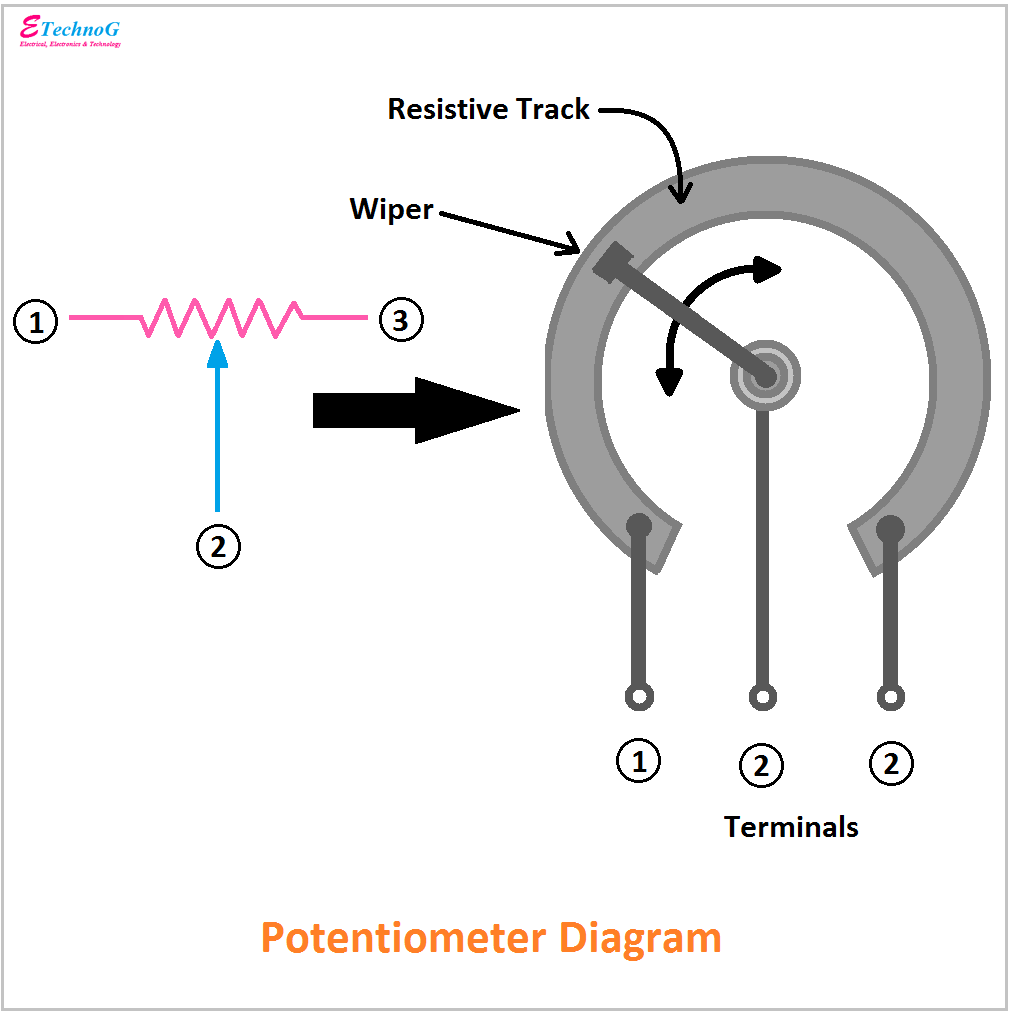
Potentiometer Diagram, Symbol, and Construction - ETechnoG

Solved: Calculate How The Output Voltage Range Would Chang... | Chegg.com

Determination of Internal Resistance of a Cell Using Voltmeter - QS Study

Resistors – Potentiometers – Basic Principles – The Passives Times
.png)
Three Ways of Connecting Potentiometer in Circuits with Circuit Diagram

Arduino variable resistor