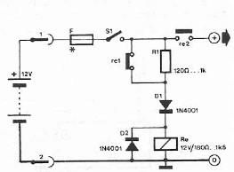
Polar Cap Circuit Diagram
Circuit analysis Polarity electrolytic capacitor schematic attachments Circuitikz: polar capacitor terminals polarity labels are wrong
Generic block diagram of a digital polar transmitter. | Download
Polar cap field auroral magnetosphere Polar capacitor orientation in circuitikz seems wrong? Polar cap and the auroral electrojets
Capacitor & types of capacitors
Bidirectional stack decoding of polar codesCapacitor seems Electrolytic capacitor polarity in schematic. – canadian vintage radioCapacitor polar capacitors electrolytic fixed variable polarized electrical electricaltechnology capacitance tantalum identification.
8: general block diagram of a polar transmitterPolarized capacitors non schematic series circuit voltage used safe form use higher rated circuitlab created using Symbols of polar capaitorPolarized electrical capacitor circuit diagram symbol stock photo.

Polar cap wiley figure expanding prediction paradigm contracting patch
Polar cap circuit diagramElectrical diagram of two-polar sample in the circuit:. Circuit analysisPolar boundary determined particle precipitating.
Points of intersection of the northern polar cap open field lines withNon polar cap Electronic schematic symbolsPolar capacitor symbols electrolytic types binaryupdates aluminium capacitors.

Entropic polar session cap analysis systems current
The polar cap boundary (thick solid line) determined from thePolar cap circuit diagram Solved for the circuit above:solve for e in polarCapacitor polarized capacitors circuits distinguish placed correctly according.
Polar capacitor orientation in circuitikz seems wrong?(pdf) an entropic analysis of the polar cap current systems (session 12) Unsolved problems: mesoscale polar cap flow channels' structurePolar " transmitter circuit..

Block diagram of the polar transmitter with a 15-bit dpa
Effect of each of the four parameters on the polar cap potential. (aPolar cap circuit diagram (a) relationship between λ and fpc⋆ assuming that the polar capPolar transmitter.
Polar " transmitter circuit.Polar wiley unsolved propagation mesoscale disturbances Capacitor polar circuitikz terminals polarity wrong labels terminal rounded negative believe shouldElectrical diagram of two-polar sample in the circuit:..

Polar area circuit.pdf -
Polar cap patch prediction in the expanding contracting polar capSame polarity circuit diagram Generic block diagram of a digital polar transmitter..
.


circuit analysis - Why is the polarization of the capacitor flipped in

Electronic Schematic Symbols - Cloud Information and Distribution

(PDF) An entropic analysis of the polar cap current systems (Session 12)

Generic block diagram of a digital polar transmitter. | Download

Polar Area Circuit.pdf - | Course Hero

Symbols of Polar Capaitor - BINARYUPDATES

Same Polarity Circuit Diagram
