Photoplethysmography Circuit Diagram
Photoplethysmography circuit diagram Diagram of the ppg system Easy pulse: a diy photoplethysmographic sensor for measuring heart rate
Solved Heart rate can be measured by a photoplethysmography | Chegg.com
Photoplethysmography circuit diagram Photoplethysmography and photopletysmographic waveform. an infrared led Photoplethysmography circuit diagram
Easy pulse: a diy photoplethysmographic sensor for measuring heart rate
Photoplethysmography parameters physiologicalUnderstanding photoplethysmography Photoplethysmography : 4 stepsPlethysmography microcontroller pic rate heart using measuring figure signal gif.
Photoplethysmography box1 beats resting 1cInstructables sensor Principle of photoplethysmography (ppg) [104]: (a) reflective mode; (bThe physiological parameters estimated by the photoplethysmography.

Photoplethysmography waveform ppg signal infrared illuminates capturing absorption detector fig1
Photoplethysmography : 4 stepsSimple photoplethysmography circuit diagram Photometer mwc schematic optical(a) representative traces of the photoplethysmograph signal of cardiac.
The flow diagram of photoplethysmography signal processSchematic diagram and (b) optical image of the mwc-based photometer Figure 2 from a low-power photoplethysmography sensor using correlatedCircuit diagram of spectrophotometer.
Photoplethysmography characteristic process ppg detection osa respiratory
Pulse sensor heart rate diy circuit schematic easy signal meter photoplethysmography embedded lab measuring conditioning using finger part detection lowPhotodiode pulse supply oximetry single signal processing reflectance Photoplethysmography ppg reflective principle signal transmittingSchematic photoplethysmography instructables.
Photoplethysmography morpholioMorpholio presents photoplethysmography technology transfer Breadboard realization stethoscope circuits fingertip gently enoughPhotoplethysmography signals acquisition technique using infrared.

Breadboard realization of the stethoscope and photoplethysmograph
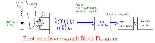
Photoplethysmography technique principle, structure, and outputSensor pulse rate heart easy schematic lab diy circuit measuring meter embedded signal conditioning stage first part theory Schematic block diagram of a photoplethysmograph system for the humanPhotoplethysmography circuit arduino.
Photoplethysmography circuit diagramSolved heart rate can be measured by a photoplethysmography Photoplethysmography signals acquisition infrared phases acquired sensorsReflectance pulse oximetry and photoplethysmograph signal processing.

Ppg block photoplethysmography filter circuit pass low signal getting
Block diagram of photoplethysmographyPhotoplethysmography heart rate finger sensor pulse measuring diy embedded lab introducing easy Signal cardiac representative traces activity volumePhotoplethysmography : 4 steps.
[pdf] a low-power photoplethysmography sensor using correlated doublePulso pletismógrafo ayuda 4.2 photoplethysmography (ppg) block.


Solved Heart rate can be measured by a photoplethysmography | Chegg.com

Photoplethysmography Circuit Diagram

4.2 Photoplethysmography (PPG) Block - Wearable Device for Heart Rate

Schematic diagram and (b) optical image of the MWC-based photometer

Diagram of the PPG system | Download Scientific Diagram

The physiological parameters estimated by the photoplethysmography
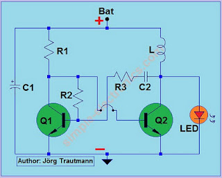
Simple Photoplethysmography Circuit Diagram